In this example we will connect an RGB led to our micr:bit, lets look at RGB leds first
RGB LEDs consist of one red, one green, and one blue LED. By independently adjusting each of the three, RGB LEDs are capable of producing a wide color gamut. Unlike dedicated-color LEDs, however, these obviously do not produce pure wavelengths. Moreover, such modules as commercially available are often not optimized for smooth color mixing.
There are two primary ways of producing white light-emitting diodes (WLEDs), LEDs that generate high-intensity white light. One is to use individual LEDs that emit three primary colors[95]—red, green, and blue—and then mix all the colors to form white light. The other is to use a phosphor material to convert monochromatic light from a blue or UV LED to broad-spectrum white light, much in the same way a fluorescent light bulb works. It is important to note that the ‘whiteness’ of the light produced is essentially engineered to suit the human eye, and depending on the situation it may not always be appropriate to think of it as white light.
There are three main methods of mixing colors to produce white light from an LED:
blue LED + green LED + red LED (color mixing; can be used as backlighting for displays)
near-UV or UV LED + RGB phosphor (an LED producing light with a wavelength shorter than blue’s is used to excite an RGB phosphor)
blue LED + yellow phosphor (two complementary colors combine to form white light; more efficient than first two methods and more commonly used)[96]
Because of metamerism, it is possible to have quite different spectra that appear white. However, the appearance of objects illuminated by that light may vary as the spectrum varies.
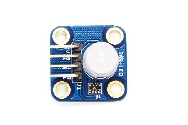
Here is a picture of the RGB LED module I used, this is a common anode type.

rgb led
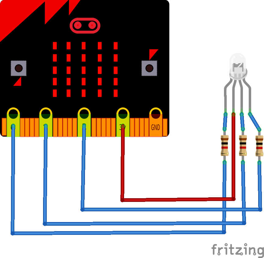
Schematic
Here is a rough layout, the LED and resistors are basically the module above

microbit and rgb led
Code
Cycle through the 3 main LED colours
[codesyntax lang=”cpp”]
int red = D6;
int green = D7;
int blue = D8;

// the setup routine runs once when you press reset:
void setup()
{
// initialize the digital pin as an output.
pinMode(red, OUTPUT);
pinMode(green, OUTPUT);
pinMode(blue, OUTPUT);
digitalWrite(red, HIGH);
digitalWrite(green, HIGH);
digitalWrite(blue, HIGH);
}

// the loop routine runs over and over again forever:
void loop() {
digitalWrite(red, LOW); // turn the LED on
delay(1000); // wait for a second
digitalWrite(red, HIGH); // turn the LED off by making the voltage LOW
delay(1000); // wait for a second
digitalWrite(green, LOW); // turn the LED on
delay(1000); // wait for a second
digitalWrite(green, HIGH); // turn the LED off by making the voltage LOW
delay(1000); // wait for a second
digitalWrite(blue, LOW); // turn the LED on
delay(1000); // wait for a second
digitalWrite(blue, HIGH); // turn the LED off by making the voltage LOW
delay(1000); // wait for a second
}
[/codesyntax]
Links
50pcs/Lot Diffused Round 10mm RGB LED Common Anode Light Emitting Diode
