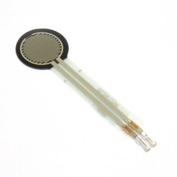
A force-sensing resistor is a material whose resistance changes when a force or pressure is applied.
Force-sensing resistors consist of a conductive polymer, which changes resistance in a predictable manner following application of force to its surface.They are normally supplied as a polymer sheet or ink that can be applied by screen printing. The sensing film consists of both electrically conducting and non-conducting particles suspended in matrix. The particles are sub-micrometre sizes, and are formulated to reduce the temperature dependence, improve mechanical properties and increase surface durability. Applying a force to the surface of the sensing film causes particles to touch the conducting electrodes, changing the resistance of the film.
As with all resistive based sensors, force-sensing resistors require a relatively simple interface and can operate satisfactorily in moderately hostile environments. Compared to other force sensors, the advantages of FSRs are their size (thickness typically less than 0.5 mm), low cost and good shock resistance. A disadvantage is their low precision: measurement results may differ 10% and more
Here is a typical example

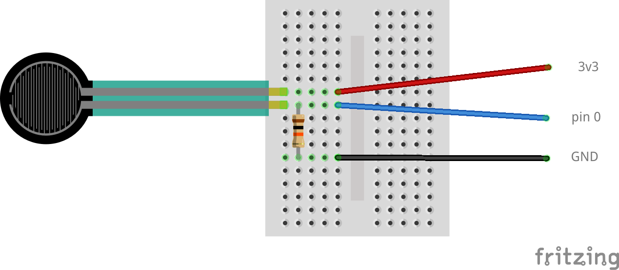
Now we will show you how to connect this to your micro:bit
Schematic
A simple layout to build here basically you are creating a voltage divider with 10k resistor and the force sensor, squeezing the force sensor alters the resistance so the voltage in at pin 0 will vary depending on the force

Code
Pretty simple example, the analog input is echoed via the serial monitor
[codesyntax lang=”python”]
from microbit import *

while True:
    a = pin0.read_analog()
    print(a)
    sleep(1000)
[/codesyntax]
Results
Open the REPL window and then squeeze the sensor, you should see something like the following
1018
1018
244
219
313
1018
1018
